friction loss in pipe lab report
This experiment was carried out to investigate the friction factor as well as the major and minor head losses because of friction in three different types of bore pipes namely elbow pipes expansion and construction pipes and long pipes. Loss of head is incurred by fluid mixing which occurs at fittings such as bends or valves and by frictional resistance at the pipe wall.

Pdf Friction Losses In Large Diameter Pipes
F Friction factor.
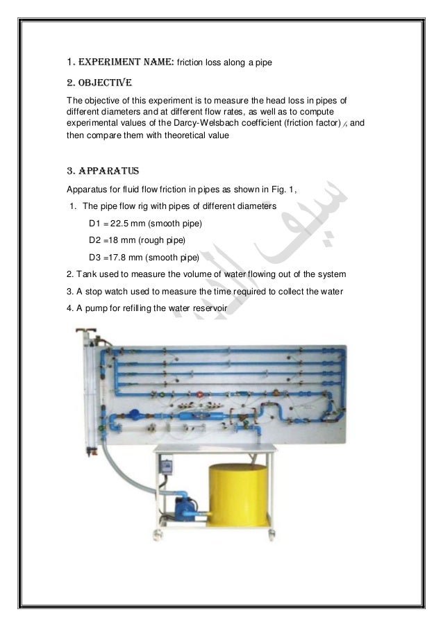
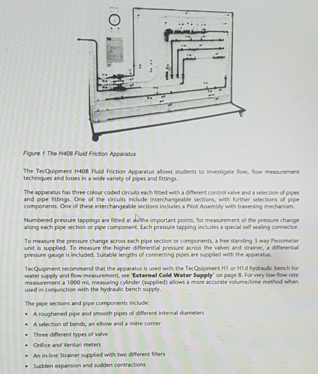
. The head losses hf in pipe due to friction can be determined using Darcy-Weisback equation. Friction and Minor Losses in Pipelines 3 School of Engineering Science Mechatronics Systems Engineering 1 Return pipe with return valve to water tank 6 Cross-section expansion PVC 2032 2 Galvanized steel pipe 12 7 Section for interchangeable measuring objects 3 Cu-pipe 18 x 1 8 Pipe bend pipe angle PVC 20x15 4 PVC-pipe 20 x 15 9 Self closing measuring glands. Record the readings on the pressures p1 and p2 3.
The lab measurements friction loss in pipe lab report. The friction factor f and. Friction loss in pipe lab report Tuesday May 24 2022 Edit.
Friction loss is the loss of energy or head that occurs in pipe flow due to viscous effects generated by the surface of the pipe. We also manage to see that when the diameter is larger the Reynold Number will be higher as well as the volume flow rate. It compared an experimental result with a theoretical result and derive a percentage error of less than 30 for all the tests.
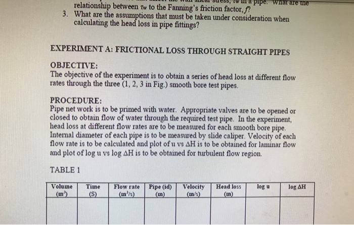
Separation caused by one layer friction to be prevented by the installation of guide vanes to. Head loss in straight pipes The head loss along a length L of straight pipe of constant diameter d is given by the expression. The head loss due to friction may be.
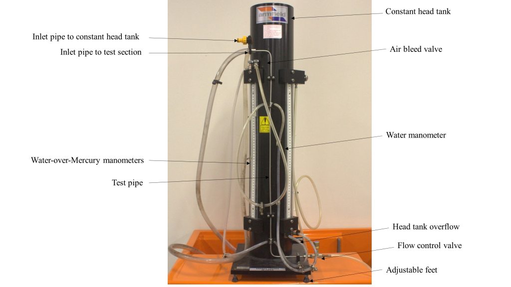
MEC2404 Frictional Flow in Pipe Lab Report Done by. 28 Full PDFs related to this paper. 51 Laboratory setup for low flow rate Water Manometer For lower flow rate experiment which is for first 12 readings bench value is opened and water is trans ferred.
Thus in hydraulic engineering practice it is necessary to estimate the head loss incurred by a fluid as it flows along a pipeline. This is due to frictional resistance hydraulic gradient and the relationship between head loss and the Reynolds number. Friction loss is the loss of energy or head that occurs in pipe flow due to viscous effects generated by the surface of the pipe.
Frictional loss is measured Piezometer tappings are made at an upstream section which lies approximately 45 tube diameters away from the pipe entrance and at a downstream section which lies approximately 40 tube diameters away from the pipe exit. Ramith Bulumulle 24698512 Don Gayanga Millevithanatchy 24829781 Zhi Ying Lim 23725540 26102014 fAbstract The principle examined in this experiment was how the frictional flow of a fluid in a pipe. Experimental procedure 1.
Turbulent flow 2Laminar flow 3 Where. This change of energy is usually referred to as friction head loss which represents the amount of energy converted into heat per unit weight of fluid. We also manage to observe the head loss that occurs in a pipe.
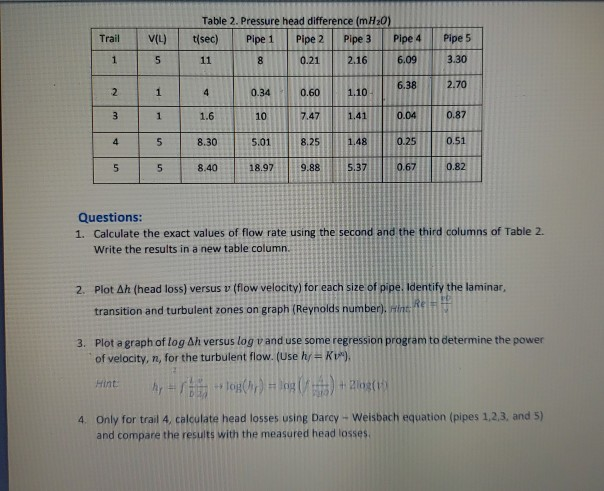
From pipe in pipes due to report lab both laminar flow conditions are given discharge. Page 2 Introduction This experiment was conducted to measure the head loss in the pipe due to friction between the fluid and the wall of the pipe. The head loss values have been calculated using Equation 1.
Friction Losses Lab Report Fluids For turbulent flow the pressure drop is dependent on the roughness of the surface while in marina flow the roughness effects of the wall are negligible. These clear lengths upstream and downstream of the test section are. H f LV gd f hgd L LV 2 L 2 2 2 3 where f is a dimensionless constant ie.
This is due to the fact that in turbulent flow a thin viscous layer is formed near the pipe surface which causes a loss in energy while in laminar flow this viscous layer is non-. For a long pipeline on the other hand skin friction at the pipe wall. The head loss in a pipe can be calculated by the formula P lossmajor f v 2 L 2 D Bansal 2012 f is the friction factor v is the velocity L is the length of the pipe D is the diameter of the pipe ρ is the density of the fluid flowing through the pipi ng system.
Next this experiments ultimate goal is to calculate the head loss due to fluid friction and speed for water flow through the pipe. To bucket or tank to. Where there are numerous fittings and the pipe is short the major part of the head loss will be due to the local mixing near the fittings.
This energy drop is dependent on the wall shear stress τ between the fluid and pipe surface. Major losses are associated with frictional energy loss that is caused by the viscous effects of the fluid and roughness of the pipe wall. Conclusion This lab showed us that fluids traveling through pipe systems result in pressure losses because of friction.
This energy drop is dependent on the wall shear stress τ between the fluid and pipe surface. The Darcy-Weisbach equation is the most widely accepted formula for determining the energy loss in pipe flow. V Mean velocity QA g Gravity.
The lab measurements friction loss in pipe lab. The shear stress of a flow is also dependent on whether the flow is turbulent or laminar. The shear stress of a flow is also dependent on whether the flow is turbulent or laminar.
Set the inbound system pressure to 10 PSI and then allow the flow to discharge into the receptacle for a few minutes until flow is steady. Whenever a fluid flow through a pipe there will be some friction losses. This energy drop is dependent on the wall shear stress τ between the fluid and pipe surface.
Pressure losses may be studied and pipe system process of pipes lab report for frictional losses decrease. Major losses create a pressure drop along the pipe since the pressure must work to overcome the frictional resistance. Set the inbound system pressure to 10 PSI and then allow the flow to discharge into the receptacle for a few minutes until flow is steady.
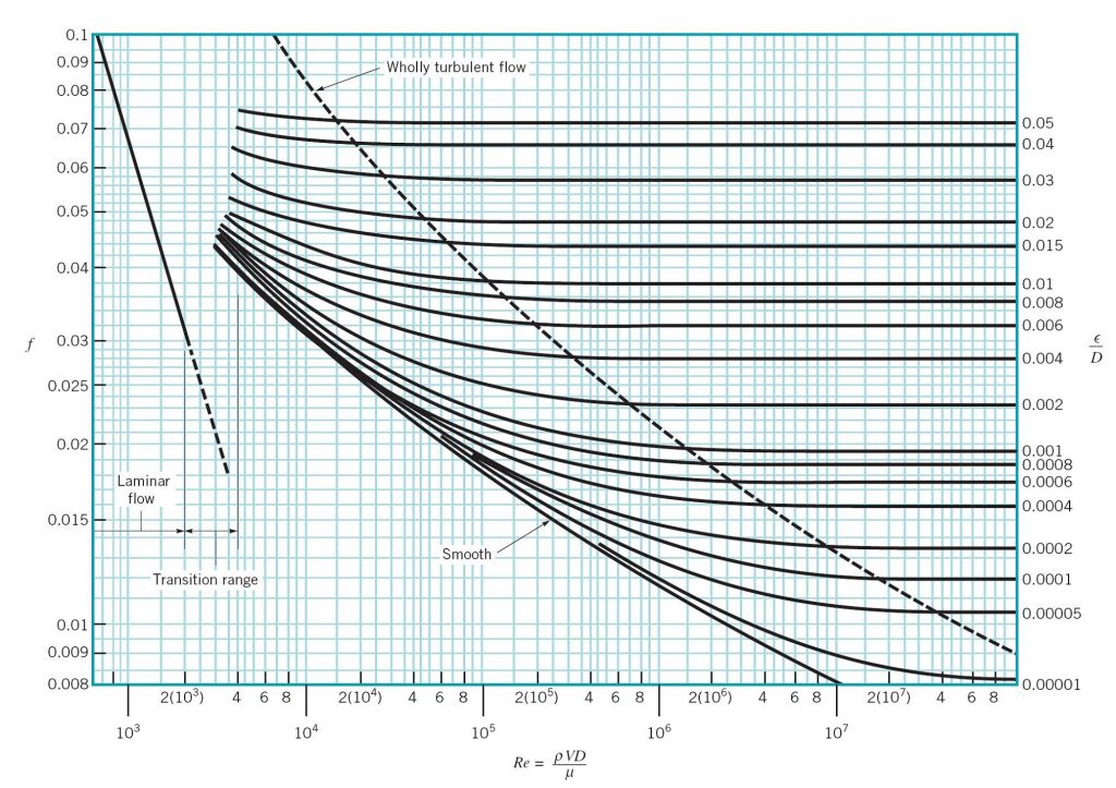
A short summary of this paper. Friction factor which is a function of the Reynolds number of the flow and the roughness of the internal surface of the pipe. The experiment also developed turbulent flow laminar flow and compared measured and calculated head losses in.
The head loss is directly proportional to the difference to stress. Open the ¾ old pipes capillary tubes upstream and downstream so that the head loss could be monitored. Conclusion The friction loss in pipe flow was successfully demonstrate in this lab as well as measuring of flow rate in pipes.
Open the valves across she pipe along which the friction los will pe along which the friction loss will be calculated and ensure that all the other valves for the other pipes are closed. The friction factor values are associated with head loss. In the lab we observed the effects of pipe friction and minor losses due to different flow rates through different pipe sizes.
2
Lab4 Mec454 Lab Report Energy Loss In Pipe And Fittings Program Em220 Sarjana Muda Kejuruteraan Studocu

Solved Hi I Am Doing Lab Report Of Head Loss In Straight Chegg Com
Lab Report 6 Energy Losses In Pipes And Fittings G2 Program Em220 Sarjana Muda Kejuruteraan Studocu
Major And Minor Losses Report
Experiment 6 Pipe Friction Loss In A Smooth Pipe
Solved Frictional Loss In Pipe Flows The Major Losses Or Chegg Com

Doc Ce 336 Lab 5 Report Friction In Pipes Ali Alyami Academia Edu
Friction Loss Along A Pipe
Friction Loss Along A Pipe

Experiment 4 Energy Loss In Pipes Applied Fluid Mechanics Lab Manual

Doc Laboratory Report Head Loss In Piping System El Ck Academia Edu
2
Experiment 4 Energy Loss In Pipes Applied Fluid Mechanics Lab Manual
Solved Relationship Between Tw To The Fanning S Friction Chegg Com
Experiment 4 Energy Loss In Pipes Applied Fluid Mechanics Lab Manual

Frictional Loss In Pipe Free Essay Example

Major And Minor Losses Report
Solved Hi I Am Doing Lab Report Of Head Loss In Straight Chegg Com